CFD Analysis of Lift and Drag on a UAV
Project Overview
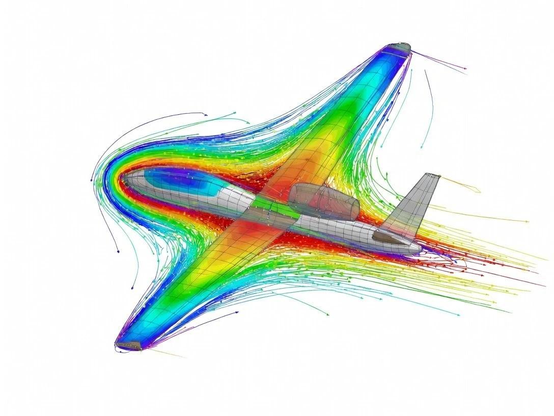
This project investigated the aerodynamic performance of an Unmanned Aerial System (UAS) using Computational Fluid Dynamics (CFD). The aim was to analyse lift and drag characteristics, validate simulation results against experimental data, and evaluate the impact of surface modifications such as wing dimples on aerodynamic efficiency.
Software
- ANSYS CFX
- ANSYS Meshing
Methods
- CFD Simulation
- Mesh Independence Study
- SST k-ω Turbulence Model
- Boundary Layer Modelling (y+ control)
Analysis
- Aerodynamic Performance Evaluation
- Lift & Drag Analysis
- Experimental Validation
Project Details
Developed a baseline CFD model of a UAS to analyse aerodynamic performance, focusing on lift and drag characteristics across varying flight conditions.
Performed a mesh independence study using a base mesh size of 0.05 m, with refinement via a Body of Influence (BoI) to 0.0125 m near the aircraft surface to improve solution accuracy.
Implemented inflation layers with a target y+ value of 10 to accurately capture boundary layer behaviour and near-wall flow effects.
Validated CFD results against experimental pressure distribution data, observing consistent trends but with discrepancies in maximum pressure due to turbulence model limitations and steady-state assumptions.
Investigated the aerodynamic impact of adding dimples at 30% chord length to assess their effect on flow behaviour and overall performance.
Compared lift, drag, and lift-to-drag ratio between baseline and modified configurations across a range of angles of attack.
Key Results
- CFD validation showed similar pressure distribution trends to experimental data, with a 55% difference in maximum pressure due to modelling limitations.
- Baseline UAS demonstrated stable aerodynamic performance up to a stall angle of approximately 12°.
- Addition of dimples had no impact on stall angle, with both configurations stalling at 12°.
- Below 10° angle of attack, dimpled and baseline wings showed identical aerodynamic performance.
- At higher angles of attack, the dimpled configuration exhibited up to 25% lower lift-to-drag ratio due to increased drag.
- Results indicate dimples did not improve aerodynamic efficiency for this UAS configuration.
Other Projects